As an intern at M3 Design, I helped develop a pitching machine for a client. We began with an off-the-shelf product as the foundation and added or modified features until we developed all the functionality required.
While my co-worker designed and fabricated a 2 degree-of-freedom (DOF) mechanism to enable a controllable pitching window, I focused on developing pitching control. For this, I started by characterizing the existing pitching machine which used a linear solenoid (a device that creates a magnetic field to exert a linear force on a plunger) to pitch the ball.

Linear Solenoid
Charcterization involved using an oscilloscope to determining transient operating voltage, peak current, output current decay as battery life wore down, and pulse-width-modulation (PWM) for variable force setting. Upon characterizing, I learned a bit about our electrical/control design - first, the peak amperage draw of the solenoid exceeded 100 amps (albeit for a very short time) and second, it became clear that the SLA battery power supply would be an issue. With continued use, power output from the SLA batteries decayed substantially and deteriorated the pitching window’s consistency. Therefore, I decided to try using a battery charging circuit to continually ‘top off’ the batteries with charge when not in use. However, this was harder than I anticipated. Lead acid batteries (as used in the device), follow a particular charging cycle shown on the below plot.

To maximize battery life, we could only perform Stage 2 or Stage 3 charge cycles. However, these stages did not provide sufficient current in the allotted charge time to replenish the charge consumed during discharge time (firing the solenoid). Further, lead-acid batteries do not have long charge/discharge life cylces and begin to degrade within 200-300 discharge cycles according to Battery University.
Therefore, I went back to the drawing board and considered an alternative - capacitors. Capacitors, by nature, are designed to handle repeated charge/discharge cycles with minimal wear and are capable of handling more current being pumped in during the charge state than chemical batteries. Due to their charge/discharge robustness], we began exploring using capacitors to provide the instantaneous peak current draw above 100A and sustain the lifespan of the device.
After sizing, ordering, and integrating the capacitors that we’d need, it certainly looked ridiculous…

…but it worked! Using MOSFETs to switch on/off capacitor charging and discharging (and frying some in the process) and an Arduino to provide the control signal, we were able to sustain a consistent pitching window and install a successful product.
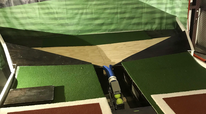
Final prototype installed and featured in local news: